ISCA CLASS RULES
Effective: March 1, 2004
(cancels previous rules and interpretations)
1. GENERAL
The Class Rules have been established to assure that the Sunfish sailboat, when raced, is
a strict one-design boat where the true test is between sailors and not boats and
equipment. No addition or alteration may be made to the Sunfish as supplied by the Builder
except as is specifically authorized by these rules.
1.1 Unless specifically prohibited, any equipment that has ever been supplied by the
Builder may be used on any boat.
2. ADMINISTRATIVE
2.1 In these rules, “Builder’ means any manufacturer duly authorized or licensed
to build the Sunfish sailboat.
2.2 Jurisdiction of the Class Rules is defined in the Constitution of the ISCA.
2.3 Identification Marks. Sunfish sailboats built prior to 1970 have an identifying serial number on a metal plate attached just forward of the daggerboard trunk. Sunfish sailboats built after 1970 are identified by the serial number on the transom. Sunfish parts (daggerboard, rudder, tiller and spars) manufactured after September, 1992 have a Class approved sticker attached. The Builder’s mark on the hull and the sticker on equipment may be considered evidence that the parts are supplied by the Builder.
2.4 In these rules, “ISAF” means International Sailing Federation and
“ISAFRR” means International Sailing Federation Racing Rule.
3. CONSTRUCTION AND EQUIPMENT RULES
3.1 Hull and Deck. The hull and deck shall be built from approved tooling
manufactured and supplied by the Builder, and shall be constructed in accordance with the
Manufacturing Specifications.
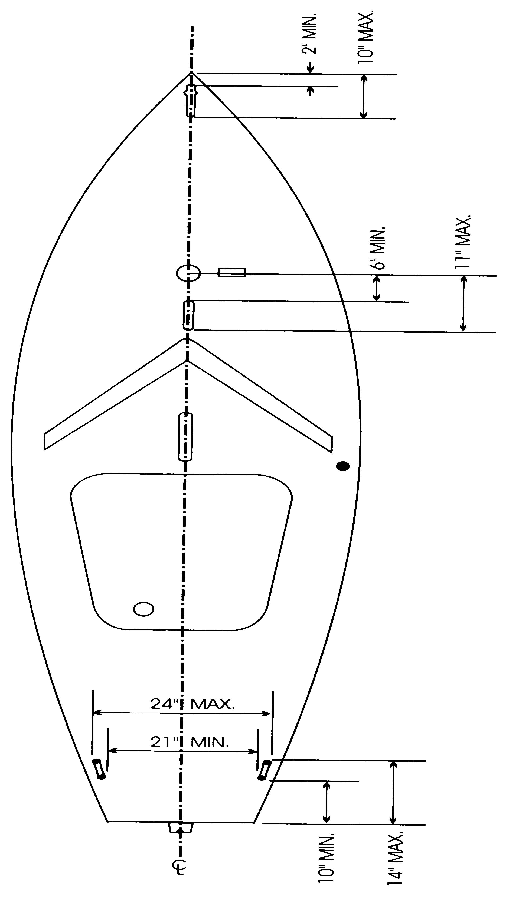
3.1.1 One single mainsheet block fitting of any type with or without an integral or attached jamming device may be mounted on the deck or cockpit lip.
3.1.2 One mainsheet cleat may be mounted on each side of the boat for the sole purpose of restraining the mainsheet. Spacers and/or wedges may be mounted under the cleats to improve alignment with the mainsheet.
3.1.3 Inspection ports may be installed on the deck or in the cockpit to provide access to the hull cavity provided that the essential watertight integrity of the hull is maintained. Removal of foam from the hull is prohibited. Inspection ports must remain closed while racing (as defined by ISAF).
Page 1
3.1.4 There are no restrictions as to the type of finish applied to the hull so long as
the finish is applied in liquid form. Materials applied in solid or sheet form are
specifically forbidden. Modification of the hull to improve the shape or performance
beyond the original is forbidden.
3.1.5 Deck fittings may be reinforced to prevent their pulling out.
3.1.6 A hiking strap making one traverse of the cockpit may be installed. The strap may be padded for comfort with any material and shock cords may be used in the attachment system.
3.1.7 A protective rubrail of any material may be mounted around the periphery of the deck. The rubrail cross section shall not exceed one inch (2.54 cm) in diameter.
3.1.8 Sanding and smoothing of the daggerboard trunk is permitted. Anti-chafe material may be added in the daggerboard trunk solely to protect the construction and finish of the daggerboard. Any material may be added to the sides of the daggerboard trunk to improve the fit of the daggerboard. There shall be at least 2 inches without the added material on each side of the trunk from top to bottom. Material shall not protrude above the deck or below the hull. Gaskets or flaps are prohibited. No changes or additions may be made that create a jibing board.
3.1.9 One or two compasses or stopwatches may be mounted on the deck so long as the watertight integrity of the hull is maintained.
3.1.10 A separate line for the sole use as a painter (bowline) may be added.
3.1.11 Clips, ties or bags may be used on the deck, in the cockpit, inside the hull, or
around the mast to stow or secure personal equipment.
3.2 Daggerboard. The daggerboard shall only be supplied by the Builder.
3.2.1 A daggerboard retaining device of any type may be used for the purpose of vertically
positioning the daggerboard providing Rule 3.2.4 is not violated.
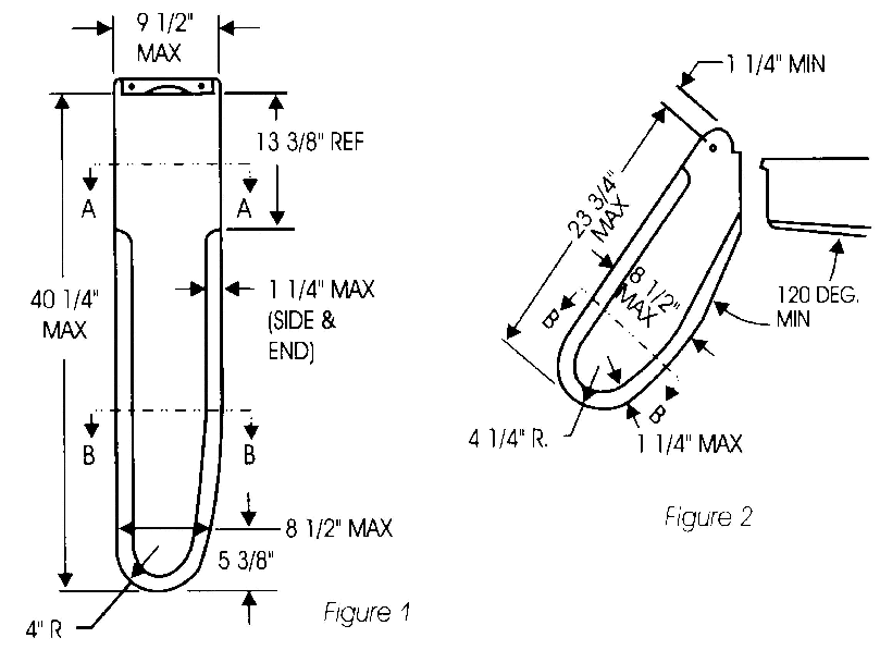
3.2.2 A handle may be attached to the top of the daggerboards (shown in Rule 5 Figures 1 & 3) for the sole purpose of raising and lowering the daggerboard.
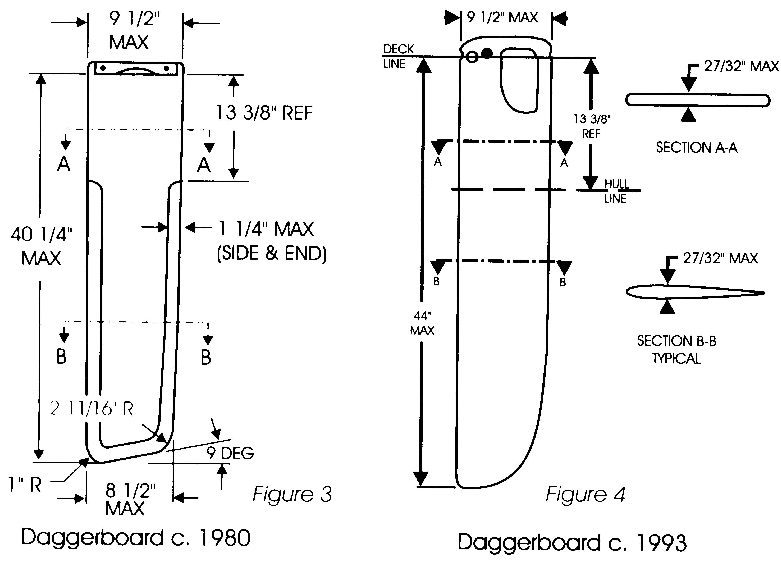
3.2.3 Minor adjustments may be made to the daggerboards (shown in Rule 5 Figures 1 & 3) by way of sharpening the trailing edge, rounding the leading edge, refinishing or repairing damage provided that the daggerboard has dimensions in accordance with the measurement diagram. Refinishing may include covering the daggerboard with fiberglass and/or resin.
3.2.4 Modifications may be made to strengthen daggerboard handles provided the distance from the underside of the handles to the end of the board does not exceed 40 ¼ inches. This applies to the daggerboards shown in Rule 5 Figures 1 & 3 only.
Page 2
3.2.5 No modifications shall be allowed to the daggerboard shown on Rule 5 Figure 4.
Refinishing and/or repairing are allowed provided that the dimensions are in accordance
with the measurement diagram on Rule 5 Figure 4 and with any gauges the Class may use to
define the original size and shape. Covering this daggerboard with fiberglass is
prohibited.
3.3 Rudder. The rudder and rudder head shall only be supplied by the
Builder.
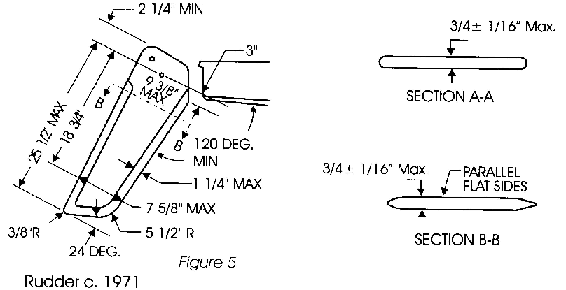
3.3.1 Subject to Rule 3.3, nothing herein shall preclude minor adjustments to the rudder
by way of sharpening the trailing edge, rounding the leading edge, refinishing or
repairing damage provided that the rudder has dimensions in accordance with the
measurement diagram in Rule 5 Figures 2 & 5. Refinishing may include covering the
rudder with fiberglass and/or resin.
3.3.2 The rudder may be reinforced with metal rods, screws or bolts to
prevent splitting. Holes in the rudder and the rudder head may be strengthened with
bushings. Bolts and nuts may be changed. Washers may be added. Plastic pads may be added
to the rudder head to reduce play.
3.4 Tiller. The tiller shall be supplied only by the Builder. Any
material may be added to the tiller for a maximum length of 16 inches to prevent chafing
from contact with the bridle. The added material should be primarily for anti-chafing
rather than for stiffening.
3.4.1 The tiller extension may be of any length, diameter or size, either fixed or telescoping, attached in any manner including a universal joint, provided it is used solely as an extension of the tiller.
3.4.2 An additional Builder-supplied tiller strap may be added to each side of the tiller.
3.4.3 Bushings may be installed in the holes in the tiller straps. The
plastic washers between the rudder and the tiller straps may be replaced by plastic pads
attached to the inner surfaces of the tiller straps to reduce play and improve rudder
reliability.
3.5 Spars. The spars and mast and all attached fittings shall be supplied
only by the Builder, except for the following changes which are allowed:
3.5.1 The location of the gooseneck fitting may be adjusted.
3.5.2 The gooseneck bolt may be replaced with any type of bolt.
3.5.3 The location of the boom blocks may be changed.
3.5.4 Attachment of boom loops mounted between the boom blocks, made of flexible material or that swing out of the way, is permitted for the sole purpose of holding the mainsheet along the boom.
3.5.5 The boom block eye straps may be replaced with any type of straps.
Page 3
3.5.6 A total of two lines and two cleats may be installed on the spars to facilitate
adjustment of tension on foot and luff of the sail. Only one adjustable outhaul/inhaul is
allowed for each spar. Lines may not be led internally in the spars. Any number of
purchases may be used. These adjustable outhauls may be led through flexible fairleads,
attached to the spars without hardware. It is permissible to use a thimble, or similar
device without moving parts, tied into the purchase loops to prevent chafing of adjustable
outhauls. This device shall not be attached to the boom.
3.5.7 Tape, plastic or similar material may be used in the following locations:
1. To fill the gap between the mast and the mast step.
2. On the upper spar to keep the halyard from slipping.
3. On the boom in the area where the gooseneck is attached.
4. On the gooseneck or mast to prevent chafing between these parts.
3.5.8 Spar and mast end caps and eye straps may be reinforced to prevent their pulling out.
3.5.9 One cleat of any type may be installed on the mast not more than four (4’) feet from the base, for cleating the line used to tie the ‘Jens Rig’ (Ref. Rule 3.7.3). It may also be used to cleat the halyard. If utilized, there must be some means to securely attach the rig to the hull using the end of the halyard.
3.5.10 Removal of any or all cork from the mast is allowed.
Additionally, a drain hole may be drilled in the mast base cap.
3.6 Sail. The sail shall be supplied only by the Builder.
3.6.1 Sails shall not be altered. Sails may be repaired providing that the shape is not altered.
3.6.2 One rectangular window may be installed in the sail so long as the shape or size of the sail is not altered. The total area of the window shall not exceed 600 sq. inches (3871 sq cm).
3.6.3 The sail shall not be attached to the spars by anything other than line and/or Builder supplied sail clips.
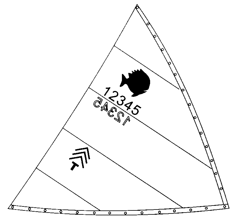
3.6.4 The class emblem shall be glued, sewn or silk screened on the sail in the second panel from the head of the sail,
3.6.5 Sail Numbers. The objective of ISCA is for members to use sail numbers assigned only by the National Sunfish Class Association (NSCA) and to require uniformity so that numbers are easy to read.
Assignment. The NSCA shall assign to each member of the
Class a unique sail number which shall be displayed on each side of the sail. This
requirement shall be strictly enforced at all World Championship qualifying regattas
beginning with new sails put into use after 1/1/96.
Size and Shape. The numbers must be easy to read, rounded in shape and of the following
dimensions: Height: 10± 1/2”, (254± 13mm), Width: 7± 1/2” (178± 13mm), and
Thickness: 1 3/4± 1/4” (45± 6mm)
Page 4
Color. For white sails, numbers shall be dark and dense, preferably
black. White numbers shall be used on dark sails. All digits on a sail must be the same
color.
Placement. Placement shall be as shown on the Measurement Diagram for the sail. Sail
numbers shall be placed parallel to and 1 ± ¼ inches (25 ± 6mm) from the center of the
seam just below the Sunfish emblem, centered under the emblem, with the number on the
starboard side placed above the seam and the number on the port side placed below the
seam. Space between adjoining numbers shall be 2± ¼ inches (51 ± 6mm).
Effectivity. The requirements for size, shape, color and placement shall be strictly
enforced at all World Championship qualifying regattas beginning with new sails put into
use after 1/1/99.
3.7 Sheets and Lines. Any sheets or lines may be substituted for those supplied by the Builder, but no additional sheets or lines, unless specifically authorized, shall be added. Sheets or lines in whole or in part of wire are prohibited except in 3.7.6. Each sheet or line must be one continuous length of line of uniform diameter.
3.7.1 The mainsheet may be any length and diameter. A purchase may not be used on the mainsheet. The trigger clip may be removed or replaced with an alternate clip of approximately the same size. A small running block may be used on the rope bridle with or without the clip.
3.7.2 The halyard may be any length and diameter. The running end of the halyard may be used as a boom vang and/or to pull the boom out in light air. A purchase may be used to draw the halyard tight, provided the sail can be readily lowered in an emergency.
3.7.3 A rig to lower the point at which the upper spar lies against the mast (known as the ‘Jens Hookansen Rig’) may be tied with an extra piece of line used solely for that purpose. The rig must be tied in such a way that the sailor may lower the sail quickly and easily by releasing the halyard.
3.7.4 The halyard may be led down the mast on either side of the sail.
3.7.5 Outhaul lines may be replaced with a line of any type and any length for the sole purpose of making a more easily adjustable outhaul / inhaul for each boom. (See rule 3.5.5)
3.7.6 Either one or both of the following bridles may be installed:
1. The wire bridle with a loop in the center, supplied by the Builder on older boats. The loop may be taped to one side to permit the mainsheet to slide the full length of the bridle.
2. The wire bridle without a loop in the center supplied by the Builder. The effective length of such bridle shall be 31 inches ± 1 inch (787.4mm ± 25.4mm) measured from eyestrap to eyestrap. The rope bridle, which was previously supplied by the Builder, is prohibited.
3.8 Wind Indicators. Any number of wind indicators of any type may be attached to the hull, deck, mast, spars, and/or sail.
Page 5
3.9 Repairs and Replacements. In the event of damage to hull, deck,
daggerboard, rudder, mast or spars, necessary repairs may be made in a manner as close as
possible to the methods and materials used by the Builder(s), and in such a way that the
essential shape or other characteristics are not materially affected. In the event of the
failure of any fitting, or the replacement of fittings as authorized by these rules, the
same or replacement thereof shall be replaced in the same position as the fitting which
failed or as close to the same position as is structurally feasible.
4. ADDITIONAL RULES WHICH APPLY WHILE RACING
4.1 One hull shall be used in a regatta or series unless approval of the RC is obtained.
4.1.1 Nothing shall prohibit two persons from racing a Sunfish sailboat provided that both persons sail together for the entire event. Class sanctioned events as defined in the class notice shall be sailed and qualified for single-handedly.
4.2 ISAFRR 45 ‘Hauling Out; Making Fast; Anchoring’, shall not apply to the International Sunfish Class unless specifically required in writing in the SI’s of a race or series of races.
4.3 The use of electronic navigational devices shall be prohibited.
5. MEASUREMENT DIAGRAMS (Following Pages)
All dimensions shown in feet and inches.
Page 6
RUDDERS & DAGGERBOARDS
ORIGINAL DESIGN
The section A-A & B-B has been redefined to ¾+- 1/16”.

Page 7
HARDWARE LOCATIONS
Page 8
DAGGERBOARDS
Page 9
TILLER AND EXTENSION

RUDDER
Page 10
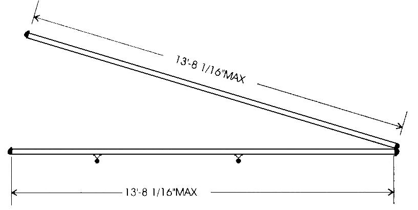
SPARS
MAST

Page 11
SUNFISH SAIL
Page 12